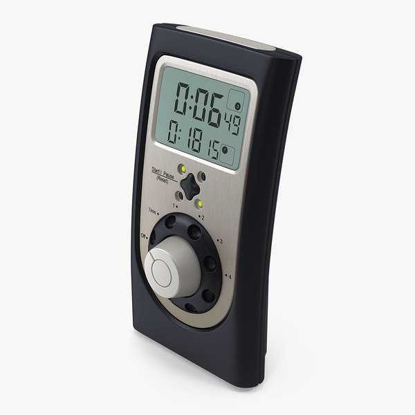
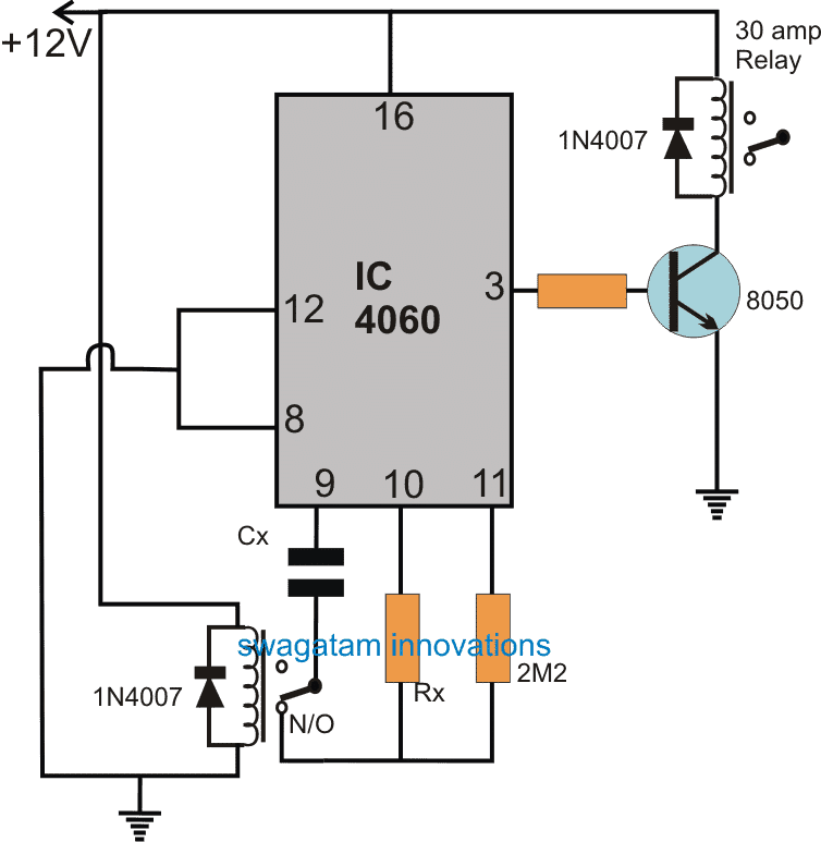
Professional digital kitchen timer 3D model Circuit Diagram It uses a 555 timer integrated circuit configured as an astable mode with frequency that can be changed by changing the values of VR1 and capacitor C1. The circuit uses a 12V DC power supply with the capacitor value of 0.1uF for a timer duration of less than 10 minutes. If longer timer of up to 100 minutes is required, use a 1uF electrolytic
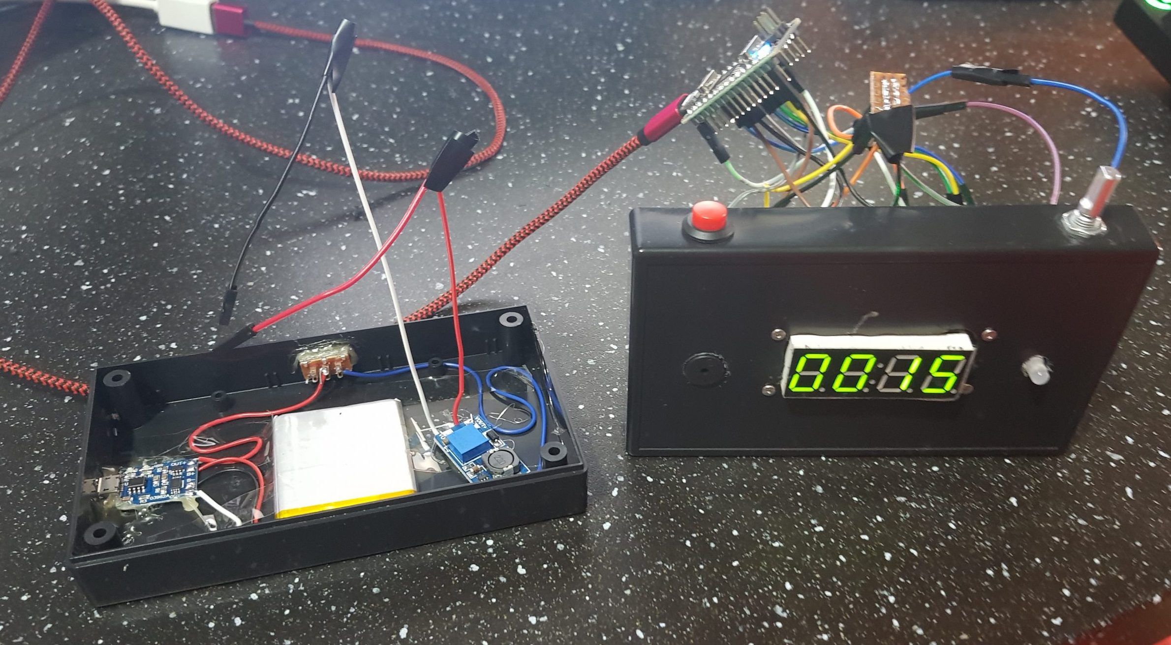
Learn how to create a digital kitchen timer, complete with a knob, buzzer, and digital display. The system has two GreenPAK IC devices, one to keep time and the other to drive the display. The schematic is shown in Figure 1. A button is configured to start, pause, continue, and reset the timer. A maximum of 1 hour (or 59 minutes) can be

Electronic Kitchen Timer Circuit Circuit Diagram
The simple digital timer circuit can obtain timing output through selectable ranges, such as 0 to 99 seconds, 0 to 990 seconds with 10 second intervals, and 0. Are; Can; How; What; The project involves building a digital kitchen timer with a knob, buzzer, and digital display using a 555 timer and a 14-stage binary counter. The system has
Build an Arduino-controlled kitchen timer and learn how to interface your Arduino with LCDs and buttons along the way. Circuit Diagram for the Kitchen Timer. First, align and place the LCD Keypad Shield directly onto the Arduino. Then connect the positive side of the buzzer to pin 12 on the Arduino and the negative side of the buzzer to the
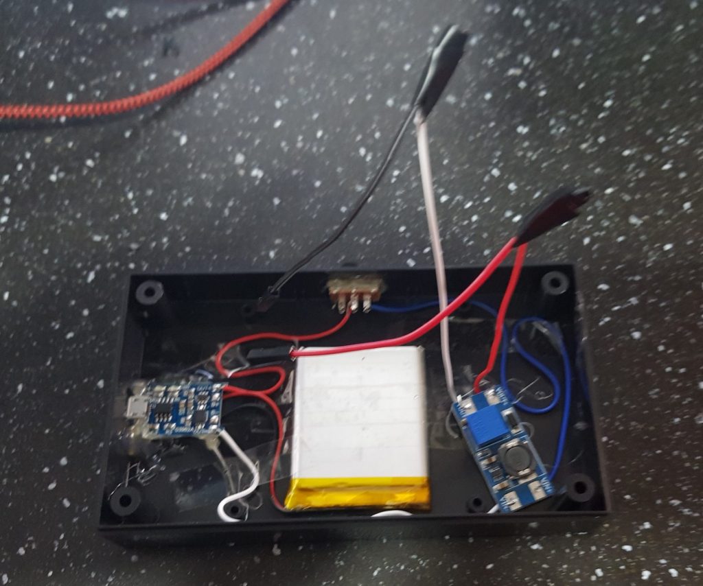
Designing and building a digital kitchen timer Circuit Diagram
In this project I plan to design and build a kitchen timer. We don't have one in our kitchen and it feels like the perfect project for a hot August weekend. This is a phenomena where by a button is pressed but due to the way the button completes the circuit at the moment on impact there is typically a bit of fluttering of pressed/not

This project steps through how to create a digital kitchen timers, complete with a knob, buzzer and a digital display. The system has two GreenPAK™ IC devices, one to keep time and the other to drive the display. The schematic is shown in Figure 1. A button is configured to start, pause, continue and reset the timer. This kitchen timer is simple enough, press and hold a button and it will count up it multiples of five minutes, until you release the button. Upon doing so the timer will flash, and begin counting down. This timer includes an alarm and a display, with a piercing piezo buzzer to get your attention. This article discussed a simple connected kitchen timer build perfect for beginners and hobbyists starting with IoT projects. However, more experienced makers can add multiple other features that enhance the finished project, for example, a custom 3D-printed enclosure that houses the electronic components.