National Instruments Circuit Diagram A Hall effect sensor circuit diagram is essential for understanding how the sensor works, and the data it can collect. Hall effect sensors are composed of semiconductor material, usually silicon. When a magnetic field is applied to the material, the electrons become unbalanced, creating a voltage difference across the two ends.
How to use Hall Effect latches and switches in practical circuits. Includes diagrams and circuits. Fig. 1. Introduction Hall Effect Switches Sensors Circuits Tutorial. by Lewis Loflin. A Hall sensor in its most basic form is an analog integrated circuit. It consists of a Hall plate that outputs a "transverse" voltage based on the intensity of a Here's an example of how you can connect this circuit to a breadboard: Arduino Hall Effect Sensor Test Code. To test the Hall effect sensor, you need to read the output pin, which is connected to Arduino digital pin 2. So basically all you need code-wise to read out the value is hallSensorState = digitalRead(D2); The hall effect sensor we will use in this circuit is an A1302 hall effect sensor manufactured by Allegro. This IC can detect magnetic fields. We will then connect this IC to an arduino, so that we the arduino can read the voltage output by the A1302 and we can display the readings to the computer screen.
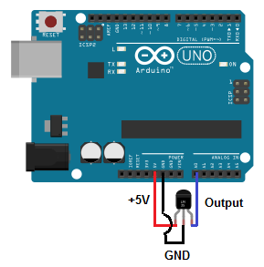
Arduino Hall Effect Sensor: How to Detect Magnetic Fields Circuit Diagram
Here we use a DRV5013 Hall Effect sensor from texas instruments, it is a digital latch Hall effect sensor. It operates with wide voltage ranges (2.5 to 38V) and provides bipolar switching. This sensor has reverse supply protection up to -22 volts and also outputs short circuit protection with current limitation features.
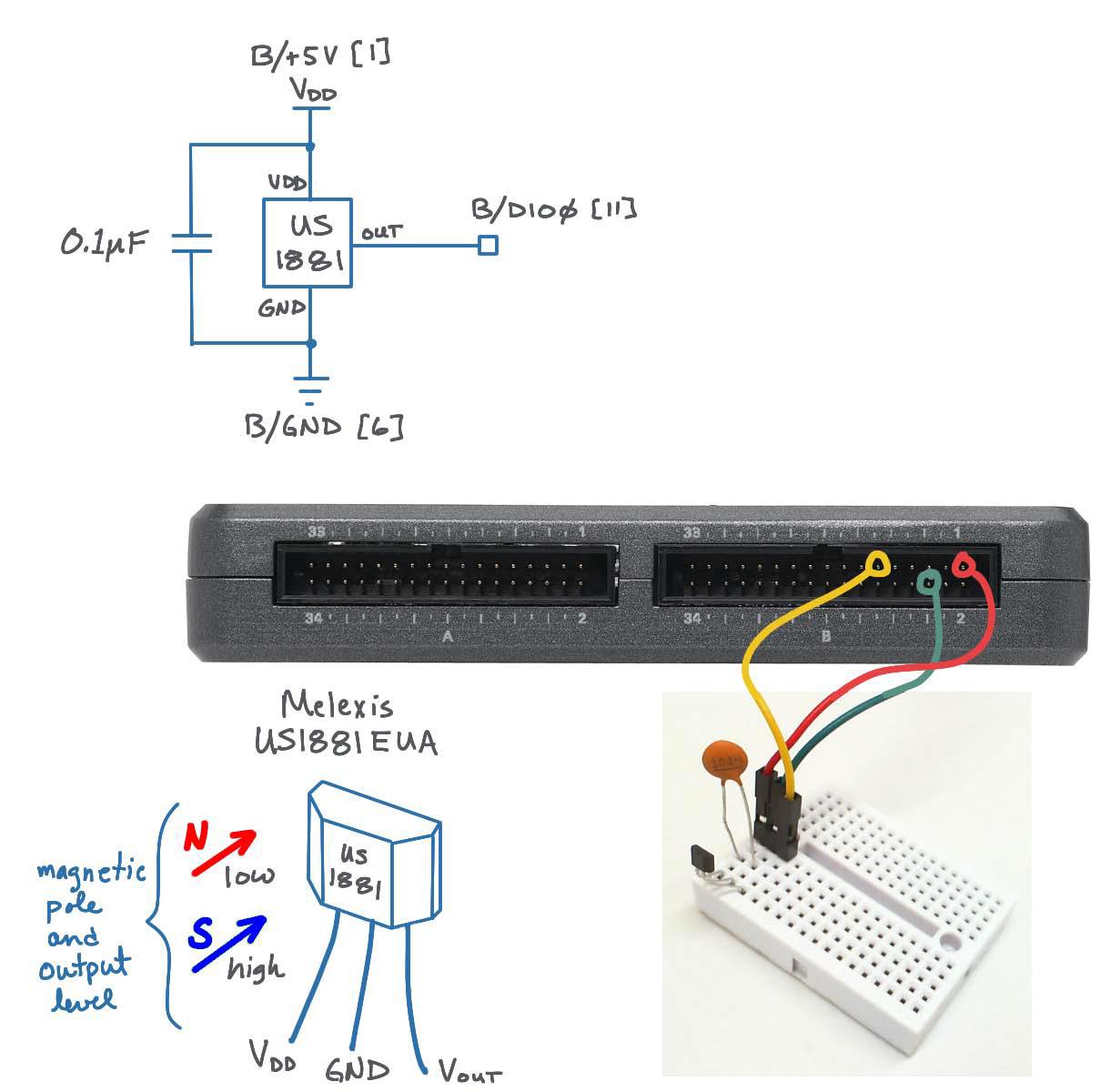
A Hall effect sensor or Hall sensor is a magnetic non-contact sensor that generates an electrical signal proportional to the magnetic field applied to it. Hall effect sensors are widely used in industrial applications like current-sensing, position detection, and contactless switching. They are basically like a small reed switch, and when a magnetic field is around, the output voltage will The GND of the sensor is connected to the GND pin on the Arduino. The Vout or signal pin of the Hall effect sensor is connected to the Arduino's interrupt pin (digital pin 2). Furthermore, a 10K resistor is connected between the VCC and Vout pins of the Hall effect sensor. This is done to pull the output of the Hall effect sensor to 5V.
![[DIAGRAM] Hall Effect Sensor Wiring Diagram Circuit Diagram](https://i.stack.imgur.com/lnbJu.png)
Multipurpose Hall Effect Sensor Circuit Circuit Diagram
If the hall effect sensor of diagram connect to RF (433 Mhz.) of diagram. Mathod: When magnet movement to hall sensor effect to RF (transmitter turn on) has signal to RF (receiver). And RF (receiver) of diagram display to LED lights turn on. Could you please write a circuit diagram for me. Thank you very much. Phuvadol (From Thailand)
