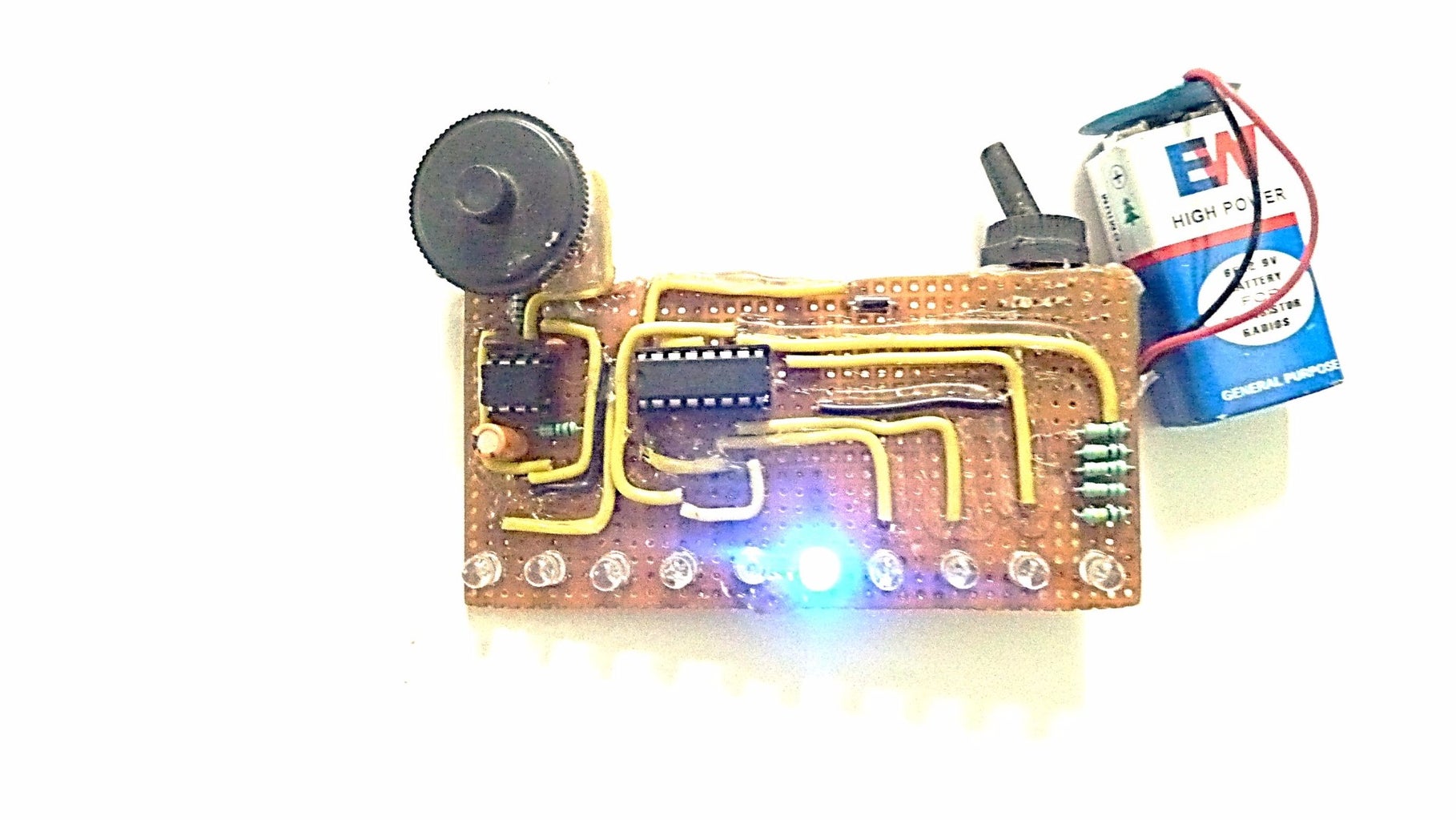
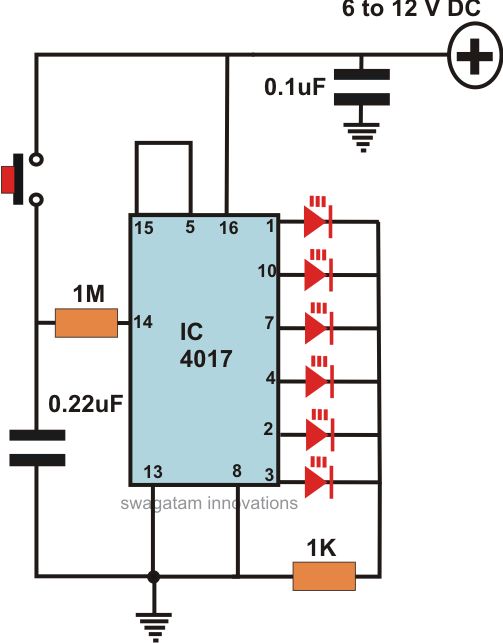
LED Chaser 5 Steps with Pictures Circuit Diagram In the next sections we will show how we can create an 18 LED light chaser by linking two of these I Cs together. Cascading Two IC 4017s for the 18 LED Effect Now if we take a look at the circuit diagram for our light chaser, we can see how the two ICs are arranged to allow for the "chasing" or "running" effect across all 18 LEDs.
The LED light chaser circuit is a popular electronic project that creates a sequential lighting pattern using multiple LEDs. This circuit is commonly used in decorative lighting and signage applications to create an eye-catching visual effect. To build a LED light chaser circuit, you will need several components: 1. LEDs:
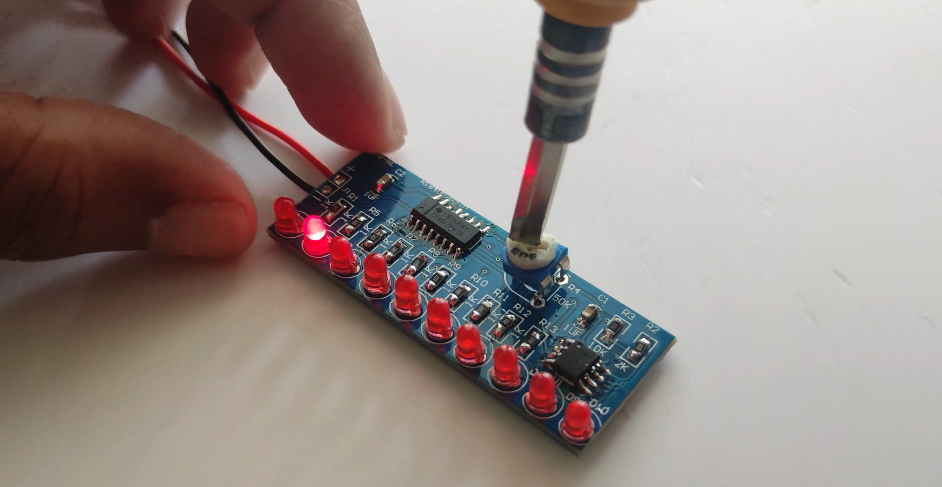
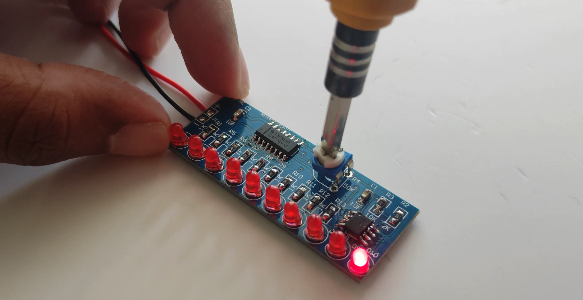
LED Chaser Circuit using 555 Timer IC & CD4017 Circuit Diagram
Working on a led chaser using Arduino. we have made an LED chaser circuit using Arduino and LED. This project is very simple and cost-effective. Components used. These are components used in the LED Chaser circuit project. Arduino; LED (different colors according to your need) Push Button; 5V battery; 220-ohm resistor; Connecting wires
📌Discover Easy, Affordable, and Reliable PCB manufacturing with JLCPCB! Register to get $60 New customer coupons: https://jlcpcb.com/?from=sritu📌Special De

How to Build an Effective LED Light Chaser Circuit: Step Circuit Diagram
Today I am going to make an LED Chaser circuit without using IC.This circuit is amazing and I will make this circuit using BC547 Transistor.This is Best LED Chaser circuit. Let's get started, Step 1: These Components Required to Make This Project. Components required - (1.) Transistor - BC547 x3 (2.) LED - 3V x6 (3.) Resistor - 560 Ohm x3 In this Instructable I show you how to make a simple LED chaser circuit. The special thing about this circuit is that it does not use an IC (Integrated Circuit). Video tutorial. By using different resistors, capacitors and transistors, I succeeded in this project to make a circuit that lights the LED lights one by one. The base of both the

1. Add LED's on breadboard according to circuit diagram connect all LED negative terminal on negative port of breadboard 2. I add LED in this pattern R G B R G B R G B But you can add LED according to your choice. 3. Now connect jumper cables on the positive side of each LED's 4. Now take arduino and connect 2nd terminals