How to assemble DIY digital clock kit Circuit Diagram In this project, I will show you how to design a simple Digital Clock Circuit using 8051 and DS12C887 as well as DS1307 RTC Modules. This article provides an overview of circuit diagrams for creating digital clocks using microcontrollers and the DS12C887 Real Time Clock (RTC) module. To create a digital clock, a microcontroller such as the Arduino Uno R3 is used as the main controlling unit.
In this project I've explained to you about how to make a simple digital clock using 8051 microcontroller with 7-segment display. By Embedotronics Technologies. In this project I've explained you about how to make a simple digital clock using 8051 microcontroller with 7 segment display.

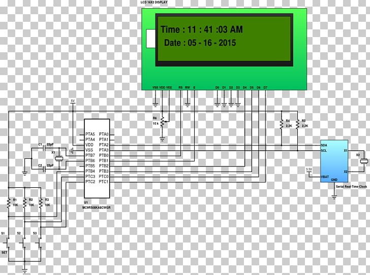
Circuit Diagram Of Digital Clock Using Microcontroller And Ds12c887
This is the circuit diagram of the digital clock using 8051 microcontroller. As we can see the microcontroller is connected to three 7 segment display with distinct ports not multiplexed and the last hour digit is only connected to a pin as it only shows 1. LED and buzzer are self explanatory according to the code. This will be a short and simple project about how to make a digital clock using Arduino. Previously We have made a binary clock using charlieplexing concept. You can find the link to that tutorial in the later part of this instructables. There are countless number of ways to make a digital clock using Arduino or say any kind of microcontroller.

Here is a simple project on how to make a digital clock with 8051 (89c51,89c52) microcontroller. The clock is efficient and their is no difference in time even in milli seconds. You can verify it with the digital clock you have. In the project i utilized the 8051 microcontroller internal clock source to produce a delay exactly equal to 1 second.
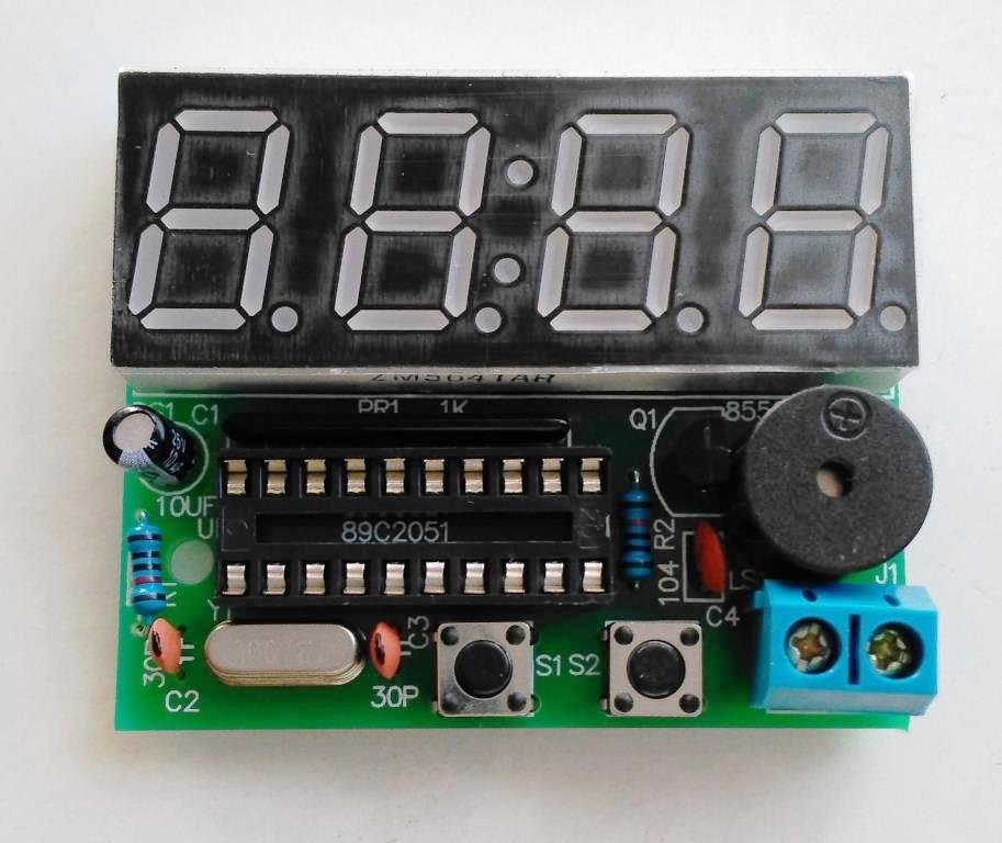
DIY Digital Clock With 7 Segment LED Display Circuit Diagram
In this project I've explained you about how to make a simple digital clock using 8051 microcontroller with 7 segment display.amazon India link to buy 8051 d