Fun with electronics and sensors Smart street light using arduino Circuit Diagram An IR sensor is basically a device which consists of a pair of an IR LED and a photodiode which are collectively called a photo-coupler or an opto-coupler. The IR LED emits IR radiation. The IR radiation is emitted in a beam from the IR LED. When this beam is disturbed, it widens and "hits" the photodiode. The photodiode converts the IR light
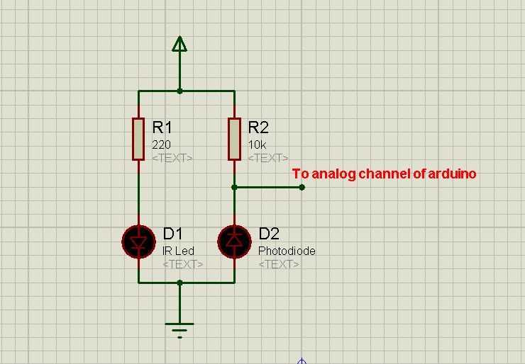
The first IR circuit will just show how the pair (IR LED & Photodiode) works. By using a transistor, we can arbitrarily amplify the analogue signal from the photodiode to power the LED. The circuit is very simple, all it needs is: Resistor: 2x 220ohm (or similar), 1x 10k. Diode: 1x IR LED, 1x Generic LED, 1x Photodiode
The Simplest IR Sensor Circuit without Arduino Circuit Diagram
The first step of our build is to assemble the components for the circuit. The main components for our IR sensor circuit are the IR sensor itself, a few resistors, a capacitor, an LED, and an Arduino board. These items can usually be found at any electronics shop, online or locally. Once we have our components, we need to connect them to the

Here you can find a wide variety of IR phototransistors at Jameco.. The circuit we will build from these parts is: IR Detector Circuit. This circuit is very simple. When the IR phototransistor isn't exposed to any infrared light, there can be no current flow through the transistor, because infrared light is what produces base current in the transistor. How to make proximity sensor. Simple IR Proximity Sensor Circuit. Diy IR Sensor ..Welcome to our channel "PendTech"I'm .Puspendu Ghosh🔘 ABOUT THIS VIDEO

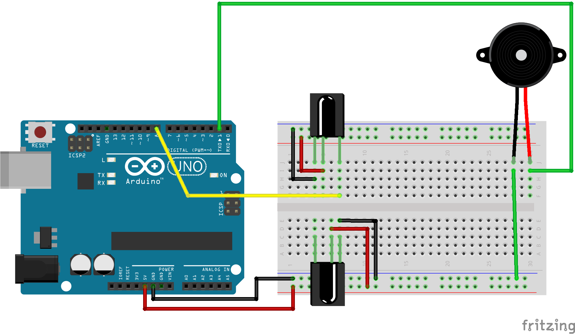
Simple IR Proximity Sensor With Arduino Circuit Diagram
This project demonstrates how to create a basic circuit using an IR sensor, buzzer, and LiPo battery, with no Arduino involved. The IR sensor triggers the bu
