Electronic Dice circuit Circuit Diagram Simple Electronic Dice: Ever wanted to make an electronic dice? I designed a simple and small circuit, that fits into every pocket.You might wounder why this is better than a normal die. It significantly increases your geekiness level.The biggest part is the battery, beca… Here is an Instructable on how to build a digital dice that uses LEDs as well as an Arduino Nano to generate random numbers and display them in vibrant colours. The housing is fully 3D printed and some circuits have to be custom made. To use the dice, a button is simply pressed and after a quick animation a number will be displayed.
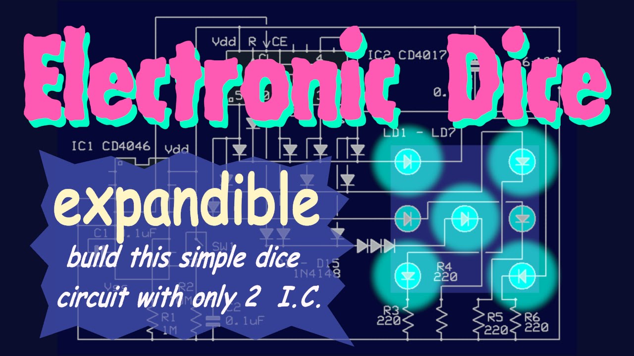
It's an open-source physical computing platform based on a simple microcontroller board, and a development environment for writing software for the board. Arduino can be used to develop interactive objects, taking inputs from a variety of switches or sensors, and controlling a variety of lights, motors, and other physical outputs. The microcontroller is the 'master mind' of the electronic dice. Microcontrollers are ground-breaking electronic parts that have a memory and can be modified to turn things ON and OFF in any require and unpredictable pattern. The microcontroller in the dice can turn the LEDs ON and OFF to show numbers somewhere in the range of one and six.

Simple Electronic Dice : 5 Steps Circuit Diagram
5 Simple Electronic Dice Circuits Explained Digital Homemade Circuit Projects. Electronic Dice Circuit Eeweb. How To Create Contactless Digital Dice Using Arduino Uno. Digital Dice Using 4017 Ic And 555 Timer Project. Electronic Dice Using 8051 Micro Digital. Electronic Dice Generates Random Numbers In The Range 1 6 Upon A Scientific Diagram. The astable multivibrator design in the formula below uses the 555 IC, which is frequently used in digital dice circuits, to determine the oscillation frequency. Let us dissect each part of the formula and discuss how it relates to the digital dice circuit: F = 1.44/(R1 + 2*RV1) * C1. where,

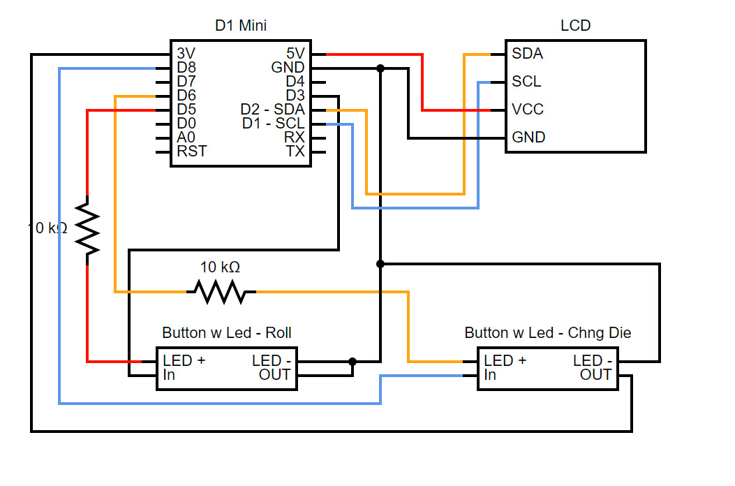
This is a very simple circuit to build and test. The electronic dice connections on the breadboard. The circuit looks a bit messy after adding the data lines for the display, so here's another image with the cables removed:
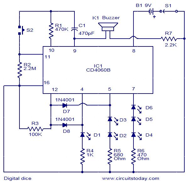
Simple Digital Dice Circuit Circuit Diagram
It is very simple and easy to construct a project on electronic dice circuit that will display random numbers from 1 to 6 on the 7 segment display. It is based on [[wysiwyg_imageupload::]]IC CD4017 and NE555. This is an alternative device that can be used to replace the traditional dice when playing games such as snake ladder, monopoly etc. While NE555 is a well known multivibrator IC, CD4107 The circuit diagram for the electronic dice using the IC 4017 is shown in the following diagram. The working of this 4017 IC based dice circuit is pretty simple. We know that when clock signals are fed at the pin#14 of the 4017 IC, the output of the IC starts sequencing forward from pin#3 towards pin#11.