basic electronics course of IR sensor remote Circuit Diagram The Serial Monitor will display the hexadecimal values of the IR codes received by the IR Receiver Sensor Module when you press buttons on the IR remote control. Step 6: Experiment and Decode. Now that the IR Receiver Sensor Module is set up and receiving IR signals, you can experiment by pressing different buttons on the IR remote control. When choosing infrared LEDs and receivers, it's a good idea to select an IR receiver that matches the LED's wavelength. The receiver should also be optimized for the carrier frequency of the protocol that'll most likely be used. Most IR receivers, however, will work fine with slight deviations from the optimal wavelength and carrier
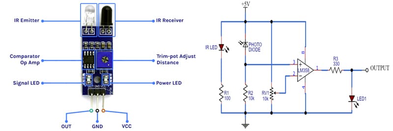
An IR sensor consists of two parts, the emitter circuit, and the receiver circuit. The IR receiver LED is used to detect IR signals, while the signal amplifier and demodulator circuit are used to amplify and process the received signal, respectively. This project demonstrates a wireless security system in which four pyroelectric There are several different types of IR receivers, some are stand-alone, and some are mounted on a breakout board. Check the datasheet for your particular IR receiver since the pins might be arranged differently than the HX1838 IR receiver and remote set I am using here. However, all IR receivers will have three pins: signal, ground, and Vcc.

DIY Infrared Remote and Receiver with Arduino and ESP 32: Complete ... Circuit Diagram
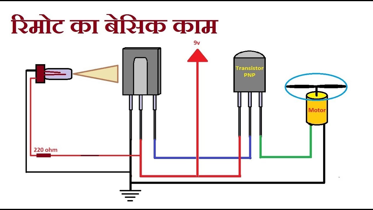
Connect the IR emitters (sometimes referred to as "IR blasters") to the emitter box. Affix each IR emitter to the proper location on each piece of gear (directly in front of the equipment's IR receiver). If your system came with an emitter that is meant to be "blasted" from a distance, then place it (or if more than one, "them In the first example, we will read incoming IR data from a common remote control using the TSOP382 IR photo sensor. The next example will show you how to transmit data from an IR LED to control a common appliance, for example your home stereo. Along with an IR receiver they can be used for remote control and even basic remote data

An IR receiver is designed to detect and decode infrared signals transmitted by an IR remote or transmitter. Here's how you can build an IR receiver using an Arduino or ESP32 board: Hardware Setup. Connect the IR receiver module to your Arduino or ESP32 board. The receiver module typically has three pins: ground (GND), power (VCC), and data I'm working on a project using the UNO where I want to detect if something moves between an infrared emitter and transmitter, similar to the way that we could tell if something passes between a photoresistor and LED. For this, I've purchased these parts: amazon.com IR receiver diode (left) and receiver mounted on a breakout board (right) They work exactly the same, so it doesn't matter which one you use. The only difference is that the breakout board often contains a small LED that blinks every time the receiver detects a signal which can be handy for debugging.